This blog post typed (slowly) with the Let's Split
Earlier this year I bought my first mechanical keyboard—a Filco Majestouch TKL with Cherry MX Brown switches. After using it for a few months, I understood the love that the MK community has for the mechanical switch—other keyboards felt limp and mushy in comparison, without the satisfying tactile bump of the mechanical switch.
After discovering the r/mechanicalkeyboards subreddit I went down the rabbit-hole, and became interested in different keyboard form-factors. A split keyboard interested me, since I've had long-running issues with RSI in my right arm which led me to use TKL keyboards in the first place. I scooped up a Mistel Barocco split keyboard and, after a few speed-bumps, enjoyed the improved hand position. But it wasn't enough—I still felt like I was reaching around too much with my right hand. What I really wanted was a keyboard which treated both hands equally.
Soon I was looking at other split keyboards, and the Let's Split caught my eye—an inexpensive, evenly split keyboard sounded just like what I was after. Unfortunately I was looking at parts right in the middle of quarantine, so supply was limited, but with some creative thinking soon I had parcels on the way from China, the US, and the UK.
A few weeks later I had all parts in hand;
- Gateron brown switches
- PBT ortholinear keycaps
- Two Let's Split PCBs
- An acrylic sandwich case
- Two Pro Micro micro-controllers
- Diodes and resistors
- TRRS cable to connect the two halves
The build
I built the keyboard following the excellent verbose guide, with some help from wootpatoot's pictures. I hadn't done any soldering for some time, but we had a nice adjustable soldering iron (actually it turned out we had three soldering irons between us), which made the job a lot easier.
After some initial humps with tip cleaning and iron temperature I was away, and the diodes were soldered in.
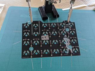
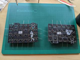
After that came the TRRS jacks, I2C resistors, and the header pins for the micro-controllers.
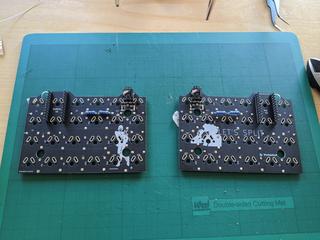
Once these were in place it was time to flash the micro-controllers. I initially tried this on Ubuntu and did not have much success, so switched to OSX and managed to get a flash first time with QMK toolkit. After this I soldered in the two switches under the controller, and the controller itself. Plugged it in and…success!
This was definitely the most gratifying point in the build! pic.twitter.com/Bc9RIlgF14
— Ben Kyriakou (@benkyriakou) June 13, 2020
The rest of the primary side was simple enough—I soldered in the rest of the switches, put on the keycaps, and it all worked!
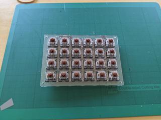
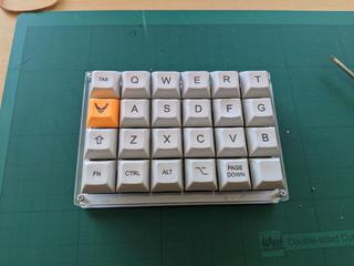
Next up was the secondary half. I flashed the micro-controller and repeated the soldering process, but trying it with the TRRS cable gave...no result? After some googling and a careful re-read of the build guide, I realised I had skipped over the line for bridging the I2C pads. A bit of unscrewing and some solder later, and we had two working halves.
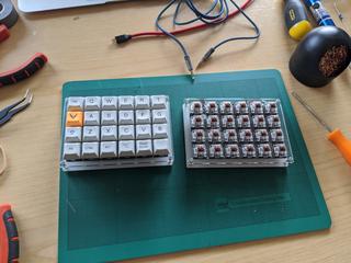
After soldering in the switches for the secondary half, re-soldering a few with dodgy connections, and adding the keycaps and the rest of the case, everything was together and working. Success!
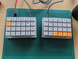
This was a fun little project, and along with my other lockdown projects has reaffirmed my enjoyment of physical making. I now need to spend some time getting used to the keyboard, but as far as first impressions go I'm enjoying the smaller footprint for my right hand.
Lessons learned
If you don't have flush-cutters, pre-cut the switch pins under the left-hand micro-controller—there is almost no clearance between the micro-USB and the PCB with standard header pins, and very little space to trim them. I also added a piece of electrical tape over the solder joints just to be safe.
Read the guide one more time. My only major mistake came from skipping over the line about the I2C pads, and I'd read the guide through a few times, so when in doubt read it one more time!
If you're out of practice with soldering, have a piece you can get set up on first—maybe something with an old or broken PCB you can solder onto. My first few solder joints would have been a lot nicer had I done this.
Helping hands are nice, but not necessary. I found masking tape and elastic bands more useful. The only step I really used them for was to thread the diodes through the PCB.
Leaded solder is unnecessary, but a small diameter is a must. The internet would have you believe that you need 60/40 solder, but I had no problems with .6mm lead-free solder. Any larger diameter though, and I would have struggled to have enough control on some of the smaller solder joints.
Get a decent soldering iron. I suspect those same people who advocate 60/40 solder are using some cheap 30W soldering iron. In my experience anything under 40W is junk, and you spend most of your time waiting for it to heat up. I'd recommend a 40W or adjustable iron with a fine tip.
Other supplies
In addition to parts and obvious tools, some things I found very useful;
- Brass tip-cleaner for soldering iron
- A small pair of metal tweezers for bending leads and manipulating components
- Masking tape and elastic bands for securing and labelling
- A work board that can take some solder beads and cutting
- Some small snips for cutting leads
- A solder sucker for desoldering (I only had to use this a couple of times, but it came in handy)